

The Crowned-Road Clearance Problem Nobody Measures Until Pickup Drops
Suction head clearance on a crowned road usually gets measured after street sweeper pickup performance drops: the sweep line runs late, dust trails behind the head, grit stays in the gutter after a second pass. By then the drop gets handled as a symptom to chase. Usually it is the last stage of a geometry problem that was built into the machine months earlier and never re-checked.
Clearance here means the vertical gap between the skirt and nozzle assembly and the pavement, measured across the full width of the head: curb side, mid-head, centerline side. It is a small number, quoted in fractions of an inch and read against the manufacturer’s figure for the head and skirt in use. It also decides whether the vacuum seals against the road and lifts material, or shears air past the edges of the head instead.
Why a Crowned Road Breaks a Single-Point Adjustment
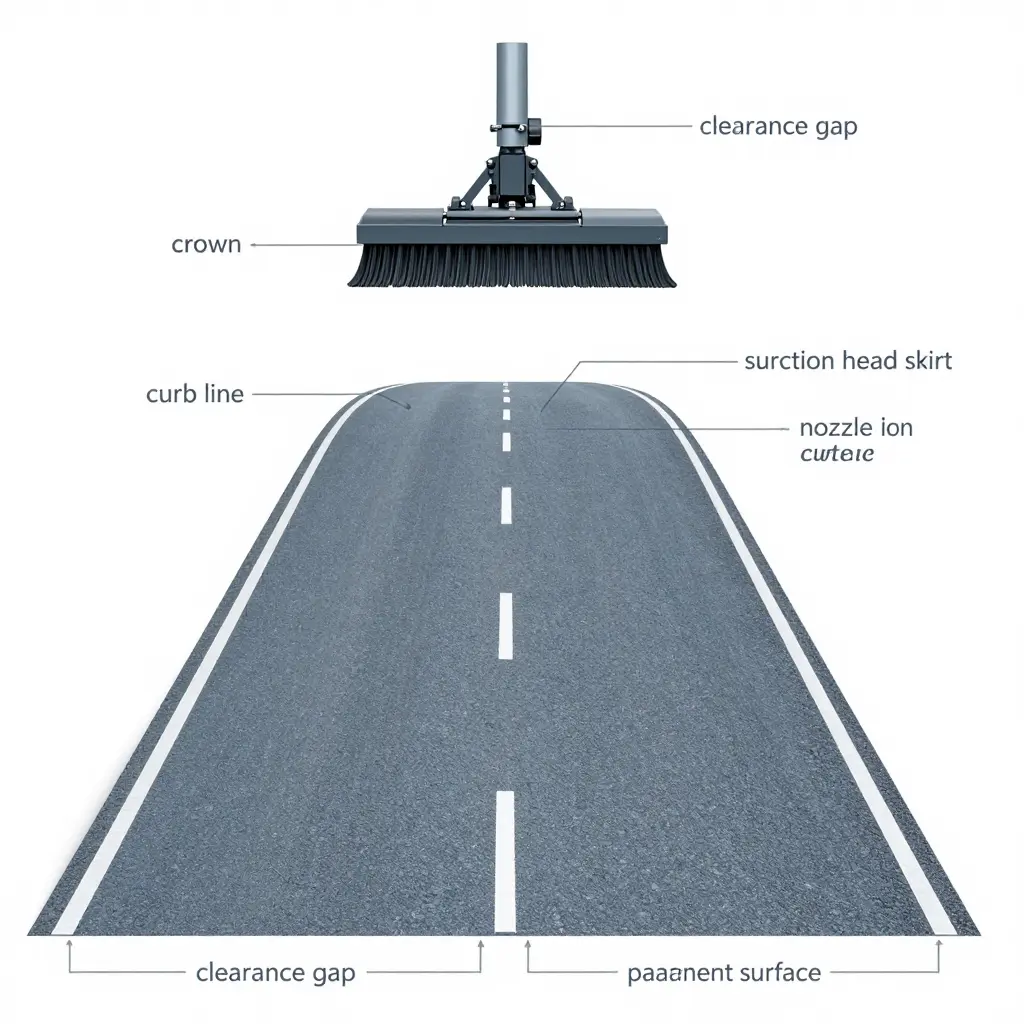
A crowned road is not a flat plane. Its cross-section runs high at the centerline and falls on a cross slope to each curb. A suction head is a rigid assembly with a fixed skirt profile and a limited range of tilt and linkage travel. No single measurement point reconciles those two shapes.
- Head set at the curb line. The curb-side skirt sits at nominal clearance and the gutter comes up clean. Move inward and the pavement drops away under the head, so the centerline-side gap opens past tolerance. Roughly half the head width stops sealing, and fines stay behind in a fan across the crown.
- Head set on the centerline side. The reverse happens. The centerline skirt is inside tolerance, but the curb-side gap has closed past it, dragging the skirt, wearing it fast, and in bad cases scrubbing the linkage and lift hardware.
- Split the difference. Both edges end up marginally out of tolerance, which reads as “acceptable” in a static check and as chronic mid-grade pickup loss in the field.
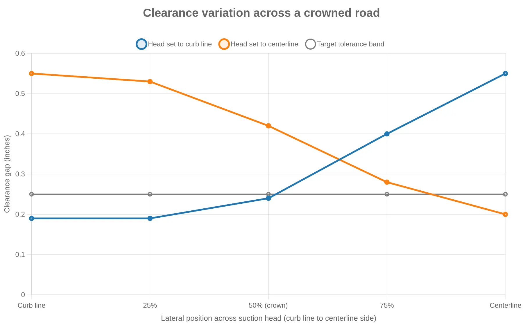
The numbers in that chart show the shape of the problem, not a specification. Correct at one edge means out of tolerance at the other, and the spread widens with crown height and cross slope.
What This Article Covers
What follows is a troubleshooting walkthrough for the shop. Four subjects, in order:
- Crown geometry against head wear. How cross slope loads the skirt and nozzle unevenly, and why the wear lands where it does.
- Measurement. Where to put the gauge, how many points to take across the width, what surface the machine should be standing on, and why one centerline reading is worthless on a crowned street.
- Wear-pattern interpretation. Reading skirt scalloping, nozzle erosion and lift-link play as evidence of a specific clearance error rather than general age.
- Correction. Adjusting tilt, skirt preload and linkage, and recognizing when a shim and an hour of labor will not bring the head back.
On older equipment the question is often whether to put money into the head or into the whole machine. Our notes on revitalizing city street sweepers cover that call before you spend shop hours on a head that is already past recovery.
Crown Geometry and Effective Head Clearance
Short version:
- Road crown is a deliberate drainage cross-slope, usually 1.5% to 3.0%, and it moves the nozzle-to-surface gap across the width of a head by tens of millimeters.
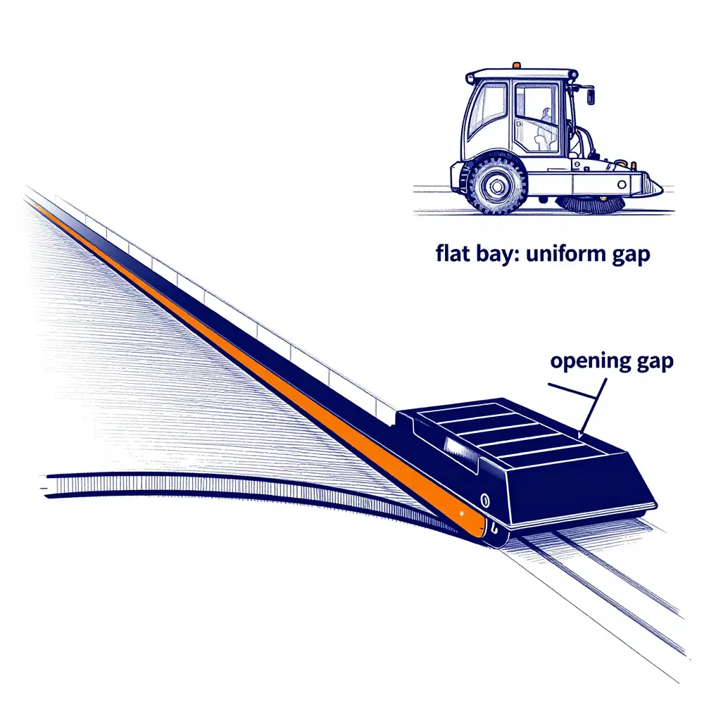
- Clearance checked on a flat bay is a static number. The same head on a crowned road runs a dynamic clearance gradient that no bay measurement shows.
- The crown side usually ends up too tight – contact and faster suction nozzle wear – while the curb side runs too loose, with blow-by, dust and lost fines.
- Because that gradient comes from geometry and not from adjustment, no single clearance setting can be right across the full road width. It can only be a deliberate compromise.
Road crown is a drainage cross-slope before it is anything else
Every crowned road is a drainage structure. Designers slope the pavement away from the centerline so water reaches the gutter before it ponds, and municipal values cluster tightly:
- 1.5% – well-drained climates, low-speed residential
- 2.0% – the near-universal default
- 2.5-3.0% – high-rainfall regions, settled or patched pavements, superelevation transitions
The profile is usually parabolic rather than two flat planes, described by a crown radius: y = x²/(2R), where the local slope at distance x from the centerline is x/R. A 7.3 m carriageway at 2% works out to a crown radius near 180 m. That matters under a sweeper: the pavement below a 2.2 m head is an arc, not a straight ramp, and a rigid head cannot follow an arc.
Static clearance on a flat bay is not the working clearance
Shop practice sets clearance on a flat concrete bay: lower the head, measure the nozzle-to-surface gap at four corners, adjust the lift linkage or caster stops, write the number down. Results typically land between 8 and 15 mm, with the tight end reserved for fine, dry grit.
That figure is a static clearance. It exists because the bay is flat. On a crowned road the head meets the plane at an angle, so the gap becomes a function of lateral position:
gap(x) = g₀ + s · x
where g₀ is the crown-side gap set at the linkage, s is the cross-slope as a decimal, and x is the offset from the crown-side edge of the head. Nothing has failed and nothing is out of adjustment. The geometry moved.
Head width and crown radius build the gradient
Because the crown falls away in one direction, the gap grows toward the curb, and head width multiplies the effect. The table assumes a 10 mm crown-side setting:
| Head width | 1.5% cross-slope | 2.0% cross-slope | 3.0% cross-slope |
|---|---|---|---|
| 1.8 m | 37 mm | 46 mm | 64 mm |
| 2.2 m | 43 mm | 54 mm | 76 mm |
| 2.6 m | 49 mm | 62 mm | 88 mm |
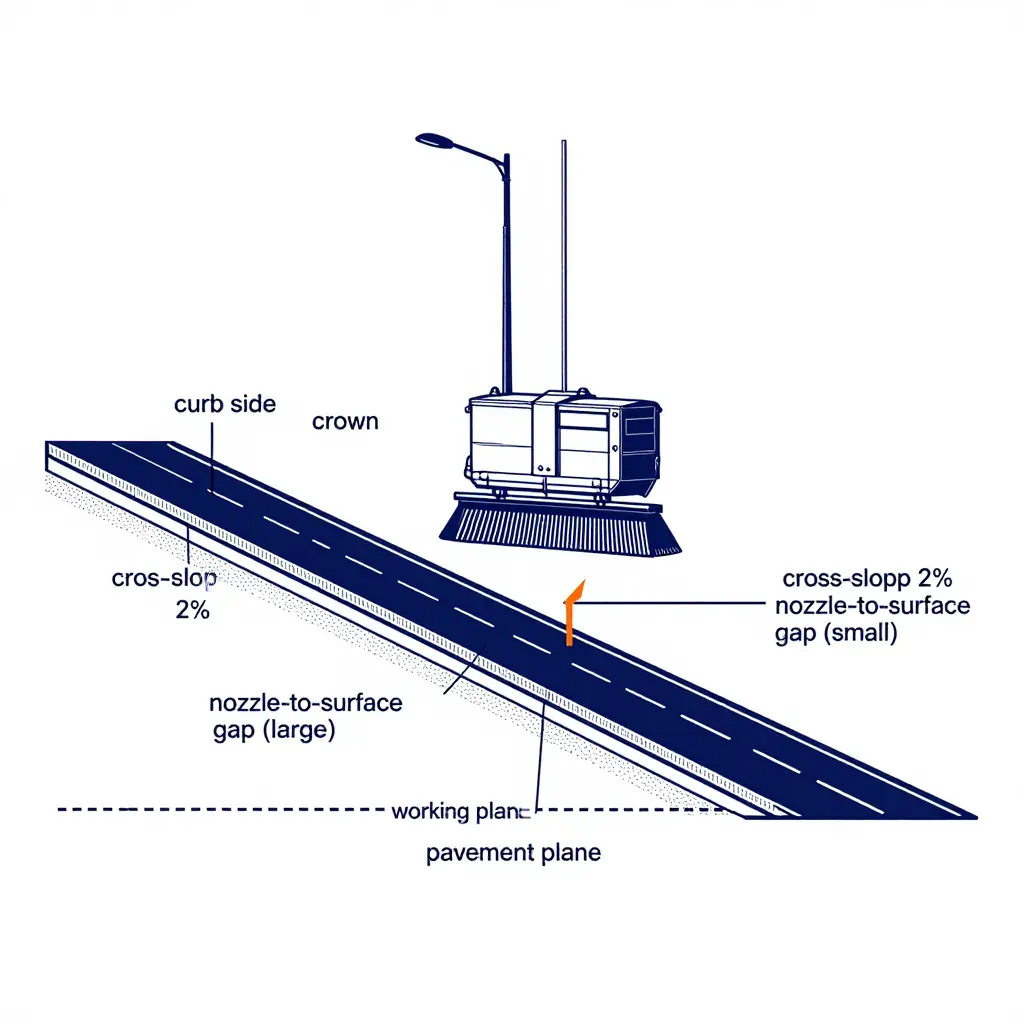
A rigid head holds a flat working plane; the pavement underneath is an arc, so the gap widens from crown side to curb side.
A tighter crown radius adds a second-order term. Over a 2.2 m span on a 150 m radius, the parabolic curvature alone adds roughly 16 mm of drop that a straight-line estimate misses. Wide heads with segmented or floating skirt sections hide part of that; single rigid blades do not.
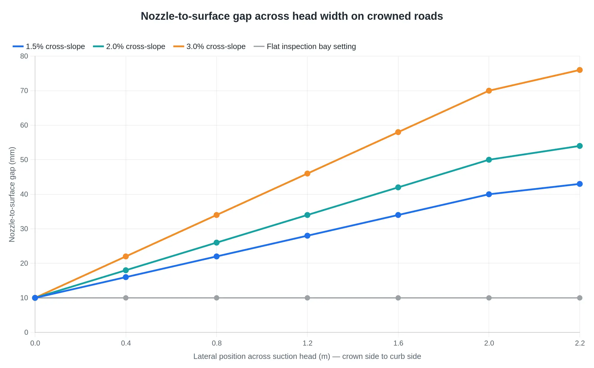
Same head, same linkage setting, three cross-slopes. The curb-side gap roughly doubles between a 1.5% and a 3.0% crown.
Suspension, tire pressure, and load distribution shift the gradient
The numbers above assume the head stays parallel to its reference plane. It doesn’t stay put.
- Suspension movement. Air-spring ride height and body roll move the whole head plane. One degree of roll across a 2.2 m head is roughly 38 mm of edge-to-edge change, enough to erase the design margin in one turn or one crowned-to-superelevated transition.
- Tire pressure. Ten psi (69 kPa) of under-inflation on a steer tire can drop the loaded radius by 5-8 mm and tilt the chassis. Uneven left-to-right pressure turns that into a permanent bias on every pass.
- Load distribution. A full hopper, a part-full water tank or a lane-side debris load changes rear-axle deflection and frame attitude. Clearance measured with an empty hopper is not the clearance running at hour six. Water-assisted units add a slow side-to-side slosh on top of a gap that was already marginal.
- Wear drift. As suction nozzle wear opens the crown-side lips and skirt, the head settles lower on that side, which deepens the gradient and speeds the next increment of wear.
Why one setting cannot be right across the road
Vacuum capture has a window, not a point. Below roughly 6-8 mm the skirt and nozzle lips run in contact with aggregate and wear accelerates. Above roughly 25-30 mm the curtain stops sealing, air short-circuits, and the head loses lift, dust control and fine pickup.
On a 2% crown with a 2.2 m head the span is 44 mm, wider than the usable window itself. No linkage position puts both edges inside it. Tighten to protect the crown side and the curb side blows dust; open up to seal the curb side and the crown side grinds. What works is a bias plus route matching, not one perfect setting.
What this means for maintenance planners
- Treat the flat-bay figure as a baseline only. Verify on a representative crowned block with a tape or laser at both head edges before the unit goes out, and put both numbers on the inspection sheet.
- Log crown percentage by route. Two-percent arterials and 3% settled residential grids need different head settings, different skirt service intervals and different pickup expectations.
- Bias the setting toward the crown side, where contact damage and suction nozzle wear start.
- Read wear patterns as geometry data. Fast lip loss on one edge with uneven skirt contact is a clearance-gradient signature, not just a worn part.
- Check ride height, tire pressures and hopper attitude at the same time. Plenty of clearance complaints are suspension or inflation problems wearing a geometry costume.
Staying ahead of this costs far less than chasing pickup complaints. Programs that rebuild heads and reset clearances on a schedule rather than on failure see fewer mid-route drop-offs; revitalizing your city’s street sweepers on a defined interval does the same for crowned-route performance.
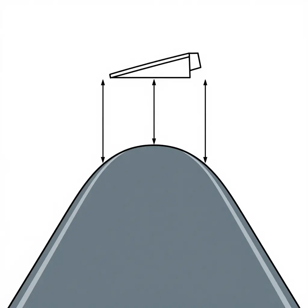
Figure: schematic only. The head sits level on the frame while the crown falls away, so the gap is small at the center and large at the outer edges. Useful when explaining to an operator or supervisor how a single center-line gauge reading can look perfect while pickup fails.
On older fleets this geometry is often where sweeper refurbishment decisions get made: rebuild the linkage and nozzle, or accept that wear on a crowned street will outrun the machine.
Airflow Loss and Pickup Failure Mechanics at the Crown Edge
No suction head has ever run with a perfectly even gap. On flat, true pavement a well-adjusted head comes close. On crowned roads it cannot, because the crown is a curve and the head is a straight beam. The machine rides level, the pavement falls toward the gutters, and whichever edge sits nearest the centerline gets the least seal and the most clearance. In the shop the head still looks aligned. At idle it still sounds normal. What changes is the physics underneath, and that is where pickup quietly goes away.
The head is a low-pressure plenum, not a vacuum nozzle
A suction head is best understood as a shallow, wide plenum hanging a short distance above the pavement. The blower pulls air out of it, so the pressure inside drops below atmospheric, and that difference does the work: air rushes in around the perimeter under the skirts and through the throat, carrying grit, sand, leaves and dust with it. Two things produce lift, and they are not interchangeable – air velocity across the surface, and pressure difference across the debris sitting on it.
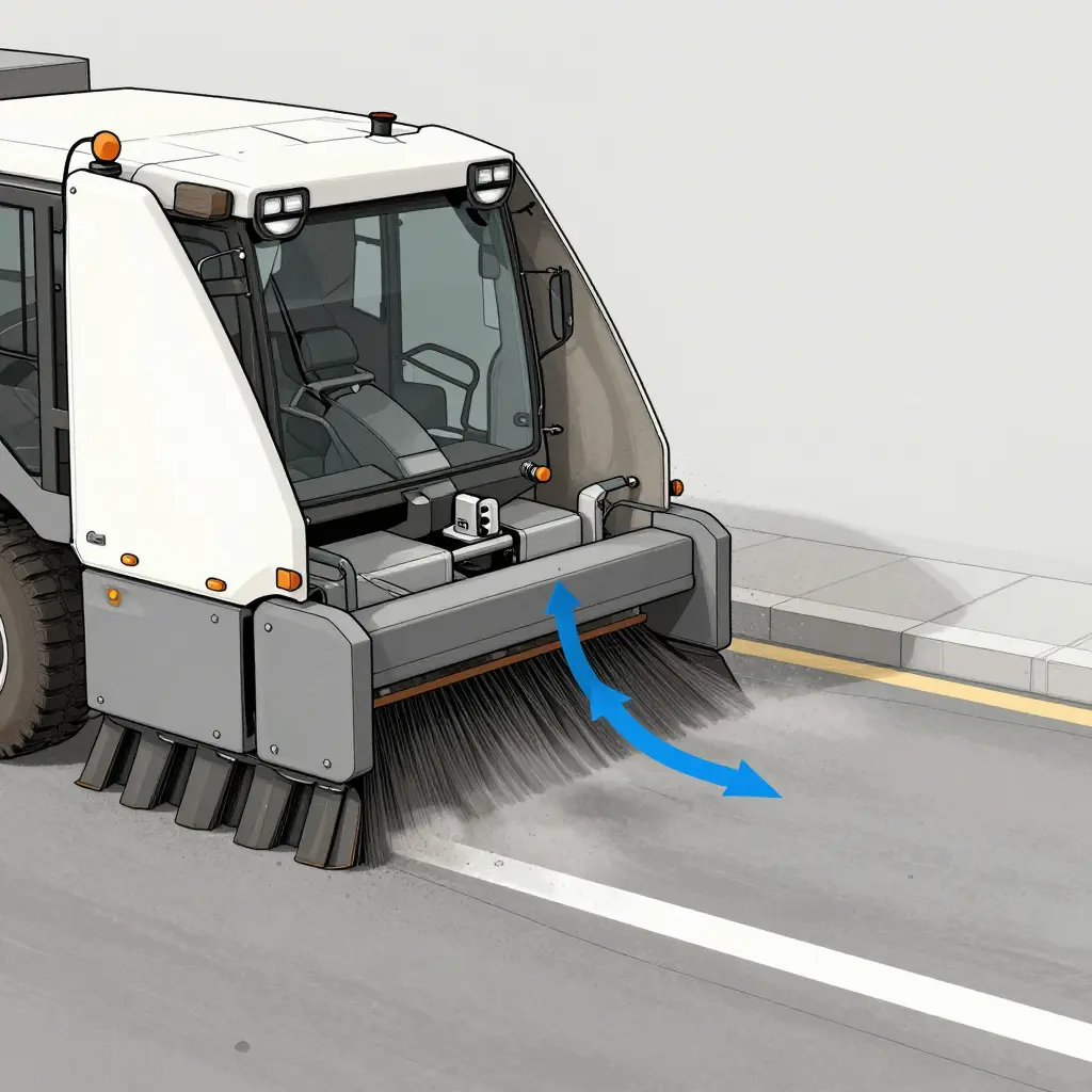
The blower moves a fixed volume of air per unit time, so every cubic meter that enters the plenum has to leave it. Sealing is what forces that airflow down against the pavement instead of letting it escape around the edges. Clearance is therefore a tuning knob, not a cosmetic dimension: it decides how much of the fan’s capacity is spent on material and how much on nothing.
When the gap opens: the short-circuit path
Air takes the path of least resistance, and a widened gap under the crown-side skirt is exactly that. As clearance grows on the high side of the crown, more of the total flow enters through that edge, crosses a short distance inside the hood, and turns straight up the throat. It never crosses the brush zone. The head has become a duct from atmosphere to blower, and the pavement under the brush gets whatever flow is left over.
This is the defining pickup failure on cambered surfaces, and it explains a pattern crews know on sight: the middle of the lane looks clean, the crown-side strip stays streaked, and the gutter edge – where the gap is tightest – often picks up better than anything else. The head is not weak. It is being bypassed.
Throat velocity collapse and re-deposition
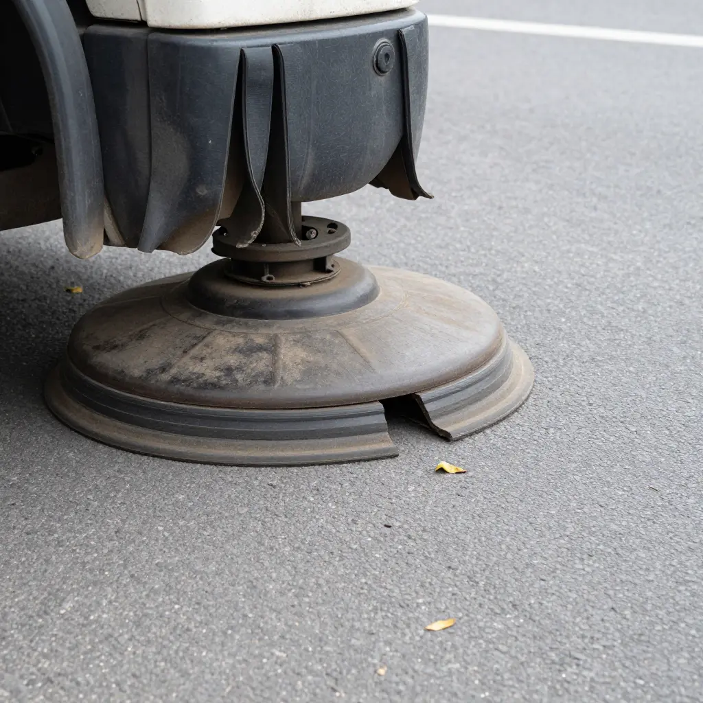
Flow through a duct obeys continuity: velocity is volumetric flow divided by area. When short-circuit flow at one edge eats a large share of the blower’s volume, the air left beneath the head slows, and throat velocity falls with it. Material gets disturbed without being captured. Leaves, litter and packaging lose the carrying capacity they need because the airstream can no longer keep them suspended. Dense grit and sand respond to local velocity right at the nozzle, so they drop out first, often while the operator is still sure the machine is working.
Rejected material does not vanish. It lands outside the effective suction envelope, which on a crowned road means the wheel path and the crown-side shoulder. Traffic then presses that grit into the surface, and every vehicle makes it harder to lift. Repeated passes over the same wheel path grind the residue instead of removing it, which is how light streaking turns into a permanently dulled lane texture.
Why skirt sealing and recirculation design change the sensitivity
Not every head degrades at the same rate when clearance drifts. The difference is in the sealing strategy. Several factors set how much a given gap costs:
- Skirt condition and durometer. Soft, segmented rubber conforms and closes the gap; hardened, curled or torn segments hang open and leak. A skirt worn short on one side is usually the first thing that opens up.
- Segmentation and overlap. More, narrower flaps follow the crown better than one rigid curtain, but more joints mean more potential leak paths if they do not overlap correctly.
- Recirculation loop design. Heads that return part of the air around the brush and reuse it keep velocity high in the working zone, which makes them more forgiving of moderate gap variation.
- Throat geometry and internal baffling. A throat placed well forward of the crown edge, with baffles that resist a direct atmospheric-to-throat path, buys tolerance when the skirt is not perfect.
This is also why a general street sweeper refurbishment program usually pays for itself in pickup quality rather than cosmetics: fresh skirts, straightened hoods and correctly set clearances restore the plenum behavior that worn hardware has been quietly destroying.
Regenerative-air versus vacuum-style heads
At a general engineering level the two families fail differently. Regenerative-air heads use a centrifugal blower moving high volumes of air at modest pressure difference, often in a closed recirculating loop. They rely on volume and on an air curtain sweeping the pavement, so a moderate gap costs efficiency but rarely kills pickup outright. Vacuum-style heads run lower volume at a much higher pressure differential and depend far more on a good seal. Because the pressure difference across the hood is the main lifting force, a large crown-side gap lets that differential collapse from the wrong end. Vacuum heads are usually the more accurate machines on tight, flat pavement and the more punishing ones to own on a badly crowned road.
| Characteristic | Regenerative-air head | Vacuum-style head |
|---|---|---|
| Primary lifting mechanism | High air volume and sweeping curtain | High pressure differential across the hood |
| Air path | Recirculating loop | Once-through to filtration |
| Tolerance to moderate gap growth | Relatively forgiving | Sensitive |
| Failure mode when gap opens | Curtain weakens, edges streak | Differential collapses, capture drops sharply |
| Crown-related wear penalty | Gradual | Marked |
Gradual, not sudden – which is exactly the problem
Pickup loss from crown-related drift does not announce itself. Blowers carry reserve capacity, so the first millimeters of gap growth get absorbed: efficiency dips and nobody notices. As the gap keeps opening, the short-circuit share of total flow grows faster than the gap, and the curve steepens – across months of service, not minutes. Abrasive grit and standing water collect at the crown-side skirt and speed its wear, the hood structure creeps and settles, the crown itself never changes, so the drift is monotonic. Nothing in the cab changes. There is no warning light for a leaking skirt.
That is why the clearance check so often happens after the complaint. By the time a supervisor stands behind the truck watching material left in the wheel path, the head has been in the bypass regime for a long time.
The loss chain, in short
- Crown geometry opens clearance at the high edge of the head while the gutter edge stays sealed.
- The enlarged gap becomes the path of least resistance, so atmospheric air short-circuits into the plenum and straight up the throat.
- Useful flow beneath the brush falls, and throat velocity drops with it.
- Lift goes before capture does, so material is disturbed but not conveyed.
- Rejected grit re-deposits in the wheel path and at the crown-side shoulder, then gets pressed into the surface by traffic.
- Skirt condition and recirculation design set how much gap the head can absorb; vacuum-style heads lose the pressure differential fastest.
- The decline is progressive and invisible from the cab, which is why pickup usually gets blamed on the blower, the speed or the operator before anyone measures clearance.
Suction Head Clearance Diagnostic Reference – Crowned Roads
Use this field card to convert what the operator sees into a clearance fault before pickup performance drops on crowned pavements.
| Head Zone | Typical Observed Condition | Likely Symptom | Probable Cause | Recommended First Action |
|---|---|---|---|---|
| Curb side | Gap within tolerance | Light residual material at curb line | Crown cross-slope | Measure and record |
| Curb side | Gap slightly over | Streaking in wheel path | Worn skirt | Replace skirt |
| Curb side | Gap clearly excessive | Visible debris trail along curb | Worn skirt | Replace skirt |
| Curb side | Gap too tight / contact | Skirt scuffing, drag marks | Damaged lift linkage | Inspect frame |
| Mid-head | Gap within tolerance | Light residual material, even pattern | Crown cross-slope | Measure and record |
| Mid-head | Gap slightly over | Streaking in wheel path | Bent head frame | Inspect frame |
| Mid-head | Gap clearly excessive | Visible debris trail mid-lane | Suspension or ride-height issue | Schedule alignment |
| Mid-head | Gap too tight / contact | Skirt scuffing at head center | Damaged lift linkage | Inspect frame |
| Crown side | Gap within tolerance | Light residual material on crown | Crown cross-slope | Measure and record |
| Crown side | Gap slightly over | Streaking in wheel path, crown side | Worn skirt | Replace skirt |
| Crown side | Gap clearly excessive | Visible debris trail plus head bounce | Suspension or ride-height issue | Schedule alignment |
| Crown side | Gap too tight / contact | Head bounce, skirt scuffing | Bent head frame | Shim/adjust |
How to use it: read the head zone and observed gap first, then match the symptom to confirm the fault class before touching hardware. Record the measured gap on every pass so the next crew can tell a crown cross-slope condition from a genuine wear or linkage failure. Related guidance on street sweeper head and wear-part upkeep covers baseline settings.
Why Routine Pre-Trip and Post-Trip Checks Miss Crown-Related Clearance Drift
What the daily check actually proves
A pre-trip walkaround proves the suction head is still bolted on. It does not prove that suction head clearance is right where it matters: where the pavement curves away from the machine. Standard inspection practice validates attachment. Crown-specific verification validates working gap. Two different questions, and only one gets asked every day.
The inspection location answers the wrong question
Nearly every daily check happens on a flat yard, apron or shop bay. Cross slope there is effectively zero, so a straightedge, a gauge block or a visual read returns a uniform number and a confident check mark.
On crowned roads the head rides a moving cross slope. The gap closes on the high side and opens on the low side, and weight distribution and linkage decide which error wins at any given moment. A machine that reads clean on the bay can be outside the working window a meter off the centerline. The measurement is accurate. The location is wrong.
Skirt presence is not working gap
A visual inspection confirms the skirt exists, hangs roughly straight and has not torn away. It cannot confirm the clearance beneath it, the sealing contact at the crown shoulder, or the local gap left by erosion and slightly bent frame rails.
Skirt rubber wears fastest where it works hardest, so two heads in identical visual condition can carry very different gaps across their width. “Skirt is present and serviceable” is a materials statement, not a clearance statement.
Operators compensate before anyone notices
Deterioration rarely announces itself. Operators drop a gear, add a second pass on the crown shoulder, nudge down-pressure, and write nothing down. The corrections are made unconsciously because the street “looks better that way”.
That is the trap. Compensation holds apparent performance steady while the gap keeps drifting. By the time the habits stop working, the head is far past its adjustment window and the crew is diagnosing a failure instead of correcting a drift.
Complaints arrive as symptoms, not measurements
A pickup complaint reaches the shop as “the sweeper missed the gutter on Elm Street”, a location and a complaint code with no reading attached. The technician starts with diagnosis rather than verification: pressure checks, hose checks, blower checks, and finally the clearance check that should have taken the first five minutes.
The records cannot close the loop
Typical street sweeper maintenance histories log a skirt replacement with a date and a part number. They rarely record the gap before and after, or the route type the machine runs, crowned arterial versus flat cul-de-sac.
Without those two fields, a rise in skirt consumption looks random rather than geographic, and no supervisor can prove that a crowned route is eating the rubber. Fleets that tighten these habits as part of revitalizing a city street sweeper fleet often recover pickup performance without buying a single part.
What the reactive pattern actually costs
Clearance verification becomes routine only after a documented pickup drop. That is a trigger, not a schedule, and waiting for it moves cost from a fifteen-minute gauge check into four channels at once.
| Cost channel | What reactive verification looks like in practice |
|---|---|
| Labor | Diagnostic hours per complaint, repeat trips, supervisor follow-up |
| Water consumption | Extra spray and dust suppression to hold down visible dust on dry second passes |
| Re-work passes | Same block swept two or three times before pickup is accepted |
| Component wear | Excess down-pressure loading skirt rubber, blower, impeller, and frame rails |
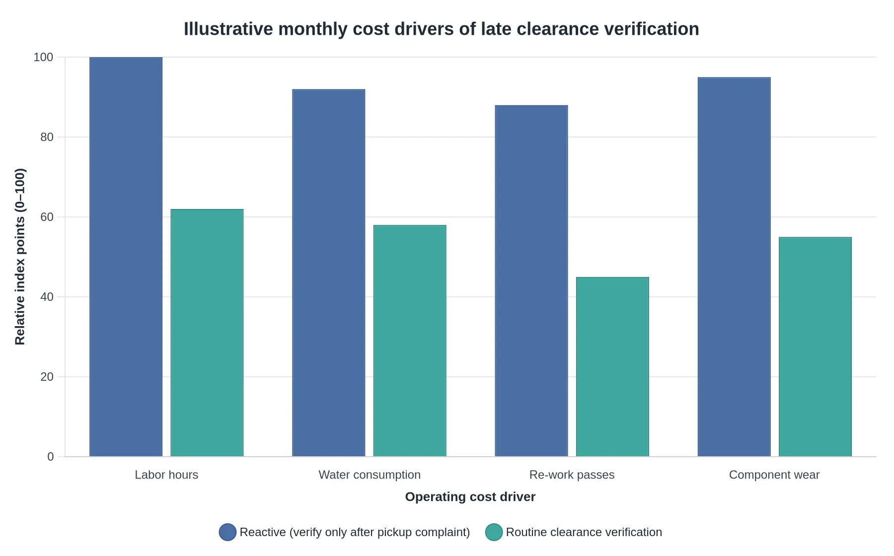
The chart is indexed, not priced: reactive labor is set at 100 and the other bars scale against it.
The conclusion: change the location and the fields
Inspection locations change first. A crowned segment of a known route belongs in the daily check, with the head measured at crown, shoulder and gutter rather than once on a flat slab. If the check cannot be done on a crown, it is not a crown check.
Record fields change second. Every skirt event should capture measured gap before and after, route type or crown condition, and what triggered the work. With those fields in place, drift shows up as a trend line instead of a surprise.
Do both and the question stops being “why did pickup drop” and becomes “what did the data say three weeks before it did”. That is the difference between maintaining a sweeper and guessing at it.
Suction Head Clearance vs. Pickup Loss: What the Numbers Actually Say
Most crews do not measure suction head clearance on a schedule. They measure it after a supervisor radios in that the sweeper is leaving a stripe of grit along the gutter pan on the high side of a crowned roadway. Wrong order of operations, and expensive. By the time pickup visibly drops, the nozzle skirt has usually been dragging, the wear strip is gone, and the blower has been working against a gap it cannot close.
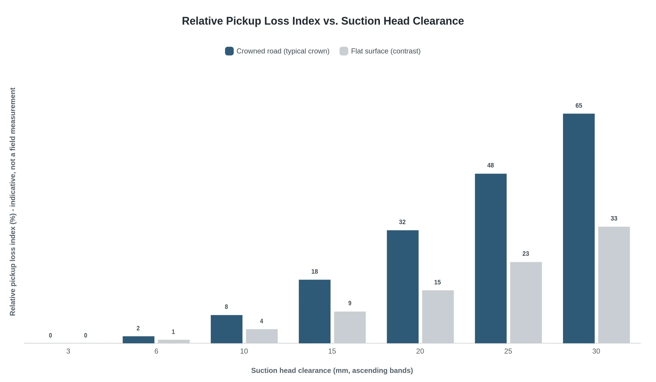
The chart below is what we use to cut that conversation short. It plots a relative pickup loss index against measured clearance in millimeters, with one series for crowned-road conditions and a second for flat surfaces as a contrast case.
A note on what the plotted values are – and are not
These figures are typical indicative trends drawn from field practice: not a manufacturer specification, not a certified test result, not an absolute field measurement. No OEM publishes a pickup loss curve for your chassis, your blower, your brush configuration and your particular pavement mix. Treat the index as a diagnostic shape rather than a hard number. It shows how steeply performance falls as clearance grows, and where the knee of the curve sits. Calibrate the absolute values against your own fleet by logging clearance and debris recovery together for a few weeks.
Reading the shape of the curve
The relationship is not linear, and that is the most useful thing about it.
- 0 to about 8 mm: the curve is nearly flat. Air velocity at the nozzle lip is still high enough to lift grit, and a few millimeters of gap is tolerable. This is the zone where a worn strip can hide.
- 10 to 15 mm: pickup loss starts climbing faster than clearance. On a crowned road the series jumps into double digits while the flat-surface series is still in single digits. This is the practical warning band.
- 20 mm and beyond: losses compound. The blower pulls ambient air from under the skirt instead of entraining debris, fine material stays in the gutter, and operators compensate by slowing down, which lengthens route time and burns fuel.
Indicative reference values
The table restates the plotted series in numbers, rounded for workshop use. Again: indicative practice trends, not a specification to hold a supplier to.
| Clearance (mm) | Crowned road – pickup loss index (%) | Flat surface – pickup loss index (%) |
|---|---|---|
| 3 | 0 | 0 |
| 6 | 2 | 1 |
| 10 | 8 | 4 |
| 15 | 18 | 9 |
| 20 | 32 | 15 |
| 25 | 48 | 23 |
| 30 | 65 | 33 |
Why crowned roads punish clearance twice
A crowned street does not present a single reference plane. The head rides a transverse slope that can run from two to four percent, and the nozzle skirt is a rigid-ish assembly trying to follow a curve. Two things happen at once.
First, the effective gap on the downhill or uphill edge of the head is larger than the gap at the crown, even when clearance has been set correctly at the centerline. Second, weight distribution shifts as the chassis leans, so the wear strip on the curb side or the crown side loads unevenly. The head measures acceptably at the gauge point and leaks air everywhere else.
That is why the crowned series separates from the flat series so early. Same machine, same blower, same nominal clearance; different geometry, different result.
A measurement routine that beats reactive checks
- Set and record a baseline on a flat slab. Park on level concrete, lower the head to the OEM setting, and measure at four quadrant points, not one.
- Measure again on the crowned route, at the same four points, loaded as it runs.
- Log the delta. A spread of more than roughly 5 mm between quadrant readings on a crowned road says the head is not following the surface, whatever the center reading says.
- Compare against the curve, not a spec sheet. Sitting at 15 mm on the high side of a crowned street means you are already giving away roughly a fifth of your pickup capacity, every shift, on every pass.
- Recheck after each wear strip change, and mid-season on routes with heavy grit loading or fresh chip seal.
Turning the curve into a work order
Clearance is a wear indicator, not a maintenance task in itself. When the numbers keep drifting back out of band, the cause is usually a worn or delaminated skirt, a bent linkage, a tired lift cylinder, or a head shell that has lost its profile. At that point repeated adjustment is just burning shop hours. If the rest of the machine is sound but the sweeping package is finished, it is worth pricing options to revitalize your city street sweepers against another season of rechecks and callbacks.
The habit that matters is the simplest one: measure clearance before pickup drops, on the surface the truck actually sweeps, and plot what you find. A crowned road will always be the harder case; the chart just makes it visible before a resident does.
The Ordered Procedure: Verifying Suction Head Clearance on a Crowned Segment
On flat pavement a single gauge reading tells most of the story. On crowned roads it tells almost none, because the same street sweeper suction head sits at a different height at the curb, at the crown, and everywhere between. The procedure below is written so a mechanic or supervisor can run it in the yard or on the route and get numbers that compare from month to month.
-
Select a representative crowned segment and record its fixed route identifier. Pick pavement with a clearly defined crown, no fresh overlay and no patching at the sampling point, then log the street name, block number and lane. A named, repeatable segment is the only way to tell real wear from a change in road geometry.
-
Stage the sweeper safely before any tool comes out. Park clear of the travel lane, set cones and warning signage well upstream, wear high-visibility PPE, chock the wheels, and apply the parking brake and lockout. Most clearance checks are done kneeling beside a machine in live traffic, so staging is part of the measurement, not a formality.
-
Establish the crown line and the curb line as references. Snap a chalk line or stretch a string across the lane from curb face to curb face, mark the crown high point, and record the distance from the curb face to that point. Without those two references you cannot tell whether a low reading belongs to the head or to where the machine was parked.
-
Place the head in working position exactly as the manufacturer specifies. Lower the street sweeper suction head to its operating position, set suspension and blower controls per the OEM procedure, and confirm the machine is at specified ride height. Clearance measured in transport position or on a half-deflated tire is a false reading that sends crews after the wrong adjustment.
-
Measure the gap at three lateral positions: curb side, mid-head, and crown side. Slide a feeler gauge or ruler under the skirt at each point and read to the nearest millimeter. Read the spread, not the individual numbers. On a straight head it follows the crown’s own fall; a twist adds a jump the crown cannot explain.
-
Repeat the reading at the front and rear of the head. Take the front and rear gap at each lateral position, giving at least five or six data points. Front-to-rear difference is the fastest indicator of a bent frame or a lift linkage pulling one corner up.
-
Record every value against the route identifier, not a vague location note. Write the numbers into the inspection form beside the segment ID, with machine hours and date; “south side of town” cannot be re-measured next quarter, and unverifiable history is why suction head clearance drifts for years unnoticed.
-
Compare the measured values to the head-specific specification. Use the tolerance band published for that head model and skirt type, not a number carried over from a different sweeper. A borrowed spec can look acceptable while the head is already out of adjustment for the crown it works.
-
Inspect for frame distortion, worn skirt edges, damaged lift linkage and ride-height deviation before touching an adjustment. Check skirt condition for suction nozzle wear, look for cracks or bends in the frame, check linkage pins and bushings for slop, and verify tire pressures and suspension height. Adjusting a head with a worn skirt or a bent frame only hides the fault, and rebuilding worn components before the season is far cheaper than repeat adjustments (see how fleets revitalize their city street sweepers).
-
Adjust in small increments and re-measure on the same crowned segment. Move linkage or skirt settings in small, recorded steps, then repeat steps 4 through 6 on the identical segment. Small steps plus same-segment re-measurement keep crown geometry out of the equation and show which change produced which result.
-
Document the before-and-after values in the asset record. Enter both sets of readings, the adjustment made, parts replaced and the technician’s name in the machine’s permanent file. That record is what turns a one-off correction into a trend line a supervisor can budget against.
| Measurement position | Primary reading (mm) | What an out-of-spec value usually points to |
|---|---|---|
| Curb side, lateral | Worn curb-side skirt, bent frame corner, linkage preload | |
| Mid-head, lateral | Baseline ride height, suspension or tire pressure fault | |
| Crown side, lateral | Frame twist, mis-clocked head, worn crown-side skirt | |
| Front edge | Lift linkage wear, bent front frame rail | |
| Rear edge | Linkage slop, dragging skirt, frame distortion |
Run this procedure every time pickup performance drops on a known crowned route, and at least once per scheduled PM interval for every sweeper assigned to hilly or heavily crowned districts. Re-check any machine that has had skirt replacement, linkage work or suspension service before it returns to the route.
Reading Wear Patterns as Evidence of Crown-Related Clearance Error
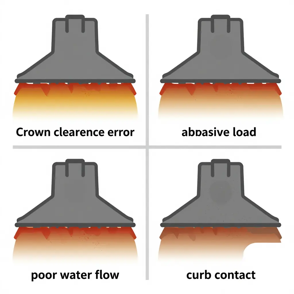
A head that has been running against a crowned road does not wear evenly, and it does not wear randomly. It wears in a signature: a repeatable, directional footprint saying the working plane was tilted relative to the pavement the head was crossing. Symmetry in wear points to abrasive load. Asymmetry points to geometry, and geometry on a crowned street almost always means clearance error at the high side of the crown.
Five Signatures That Point at the Crown
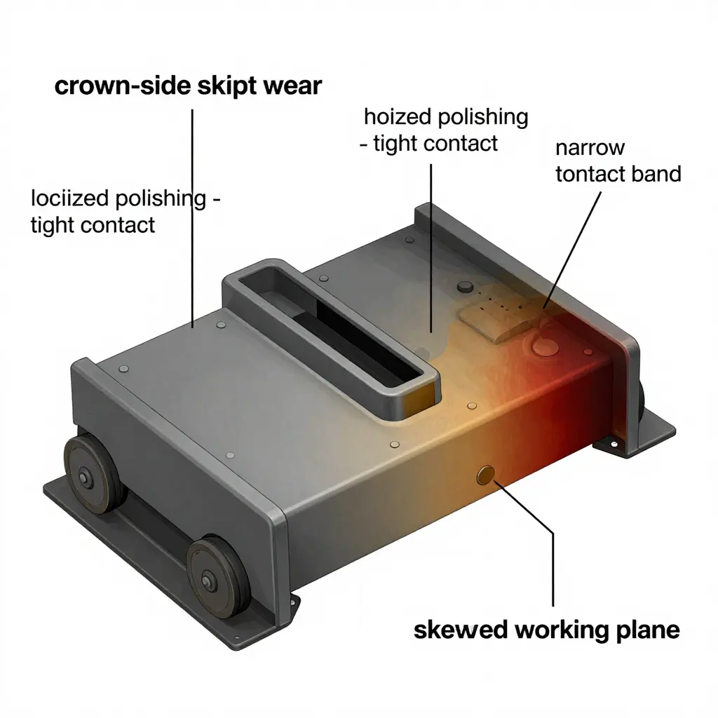
- Asymmetric skirt or flap wear. The rubber skirt on the crown side of the street sweeper suction head is abraded to a feathered, square-shouldered profile long before its opposite number. If you flip the skirts left to right and the wear follows the side of the machine rather than the skirt, you have confirmed a machine-side clearance problem rather than a bad part.
- Localized scuffing or polishing where the head runs too tight against high points. A dull mirror finish on the deck edge, the flap face or the frame rail means continuous light contact under pressure with little grit between the surfaces. Scuffing is the other case: grit-loaded contact, shorter, deeper, directional scratches. Both cluster at the crown-side high point.
- Fast gauge or nozzle-edge wear from grit concentrated in a narrow band. When the capture slot closes down on one side, the same air volume is forced through a smaller opening. Velocity rises, grit accelerates through a narrower curtain, and suction nozzle wear bores into a stripe instead of spreading across the full width.
- Elongated wear on one side of the head frame. A long, straight, one-sided wear track on the frame or wear strip is the physical record of a skewed working plane. The head is not just low, it is low in one direction, so the contact path stretches along the direction of travel.
- Bristle or curtain contact patterns. Look at the gutter broom and the rear curtain. A broom leaving a thin polished arc on the curtain, or a curtain frayed along one lower corner, is reporting that head geometry and broom geometry disagree about where the road surface is.
Mechanical Reasoning Behind the Signature
The head is a plenum, and the skirt curtain plus nozzle slot define the inlet. Capture depends on a clearance window small enough to keep air velocity high and large enough to pass debris without stalling the curtain. Roads are built with crown so water drains, so a head trimmed level on a flat shop floor is already wrong the moment it crosses the crown line. On the high side the road climbs toward the head; on the low side it falls away. One skirt drags under preload while the opposite skirt leaks air, which is why the low side often shows dust streaking and the high side shows erosion.
Grit erosion is aggressive because the concentration effect compounds: narrower slot, higher velocity, more particle impacts per square centimeter, faster loss of the steel that defines the slot. Wear then feeds back into performance. The slot opens on the eroded side, velocity drops, pickup falls off, and the operator compensates by lowering the head further, which tightens the crown-side contact again. That loop is why clearance checks only get performed after pickup drops.
Telling Crown Wear Apart From Everything Else
| Signature | Crown clearance error | Abrasive load (sand, mill tailings) | Poor water flow | Curb contact |
|---|---|---|---|---|
| Distribution | One-sided, heaviest on crown side | Broad and roughly even across the width | Patchy, with dust and mud buildup | Confined to outer corner or edge |
| Texture | Polish plus fine directional scuff | Uniform frosty erosion | Dull smears, caked fines | Gouges, dents, torn rubber |
| Nozzle edge | Narrow eroded stripe | Even edge recession | Little edge loss, heavy buildup | Local chips at one point |
| Route correlation | Repeats on crowned or cross-sloped segments | Follows material type, not geometry | Follows dry or debris-heavy runs | Follows tight turns and parking lanes |
| Driver report | Chatter, bounce, strip left on high side | Steady loss of pickup, no vibration | Visible dust plume, wet slurry | Impact noise on turns |
Correlating Wear Location With Route Geometry and Driver Reports
Before condemning a head, plot the wear. Walk the primary route and note crown height, cross-slope, and where the machine runs the gutter versus the travel lane. If the wear band is on the left side of the head, ask whether the truck runs the crown line on its left for most of the shift. Then compare what drivers say. Operators rarely use the words “clearance error,” but they will tell you the head is chattering, that it bounces over a crown, that one side leaves a strip, or that the machine pulls and needs steering correction. Matched to a specific set of blocks, those reports turn a vague complaint into a measurable geometry finding.
Weld Repair or Replacement
The answer depends on whether the wear is dimensional or structural. Weld repair makes sense when wear is confined to a replaceable plate, skirt or flap mount, when the base metal is still sound, when the deck is flat and the nozzle edge still holds its intended section, and when the repair will not put heat distortion into the airflow surface. Rebuild it, then re-trim the head to the crown with a proper clearance check rather than a level-floor setup.
Replacement is the honest answer when the deck is dished, when the nozzle edge has eroded past its section so the widening cannot be welded back, when fatigue cracks are spreading into the frame, or when the head has already been welded twice and the geometry no longer holds. In those cases weld repair re-creates the leak path that caused the wear. Whichever route you take, the wear pattern is your warranty claim: photograph it, record the route segment, and file it with the machine so the next street sweeper maintenance interval starts from evidence instead of guesswork.
Practical Takeaway
Crown-driven clearance error leaves an asymmetric, high-velocity, one-sided wear fingerprint. If the signatures above match, don’t start by replacing skirts. Re-establish the working plane against the actual road first, then judge repair versus replacement on the condition of the deck and nozzle edge.
Suction Head Underside: Wear Zone Reference Schematic
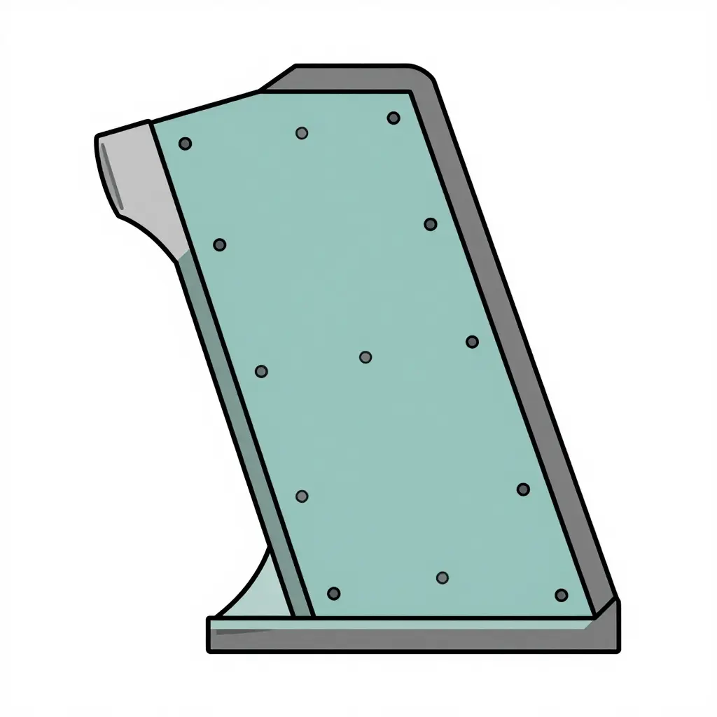
Use this schematic as the anchor for the clearance check. The darker tints mark where the head shell and flap edges take the worst abrasive contact, the mid tone follows the skirt contact lines, and the lightest tint covers the low-pressure channel that only polishes when clearance opens up. The evenly spaced circles are the measurement stations, so readings are always taken at the same points and the trend, not the single number, tells the story.
Pair the drawing with a straightedge, a taper gauge and a fixed log sheet. When the pickup pattern starts failing on crowned pavement, the shaded zones are where the geometry drifted first, and knowing that keeps crews from chasing a hydraulic fault that was never there. For a broader look at keeping sweepers productive through a full service life, see our notes on revitalizing your city street sweepers.
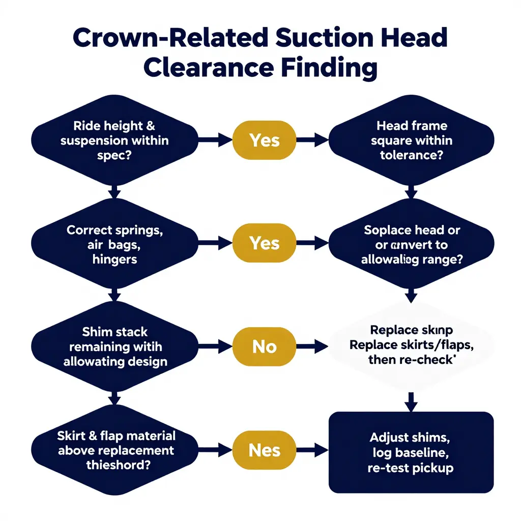
Adjust, Shim, Straighten, or Replace? Decision Criteria After a Crown-Related Clearance Finding
A clearance problem on crowned roads almost always arrives the same way: the operator reports dust trailing from one side of the head, a wet strip the vacuum will not lift, or a growing pile of grit against the curb. The instinct on the shop floor is to shim the head down and get the truck back on route. That instinct is right about half the time. The other half of the time, shimming pushes a chassis, frame or sealing fault deeper into the machine and costs pickup performance for months.
Fix the vehicle before you touch the head
Measure suction head clearance only after the chassis is proven. Check static ride height left to right at the frame reference points, air bag pressure and leveling valve function, spring sag, tire inflation and matching sizes, and the condition of the head hanger brackets and lift linkage. A truck sitting 15 mm low on the curb side will drag the gutter edge of the head while lifting the road-side skirt, and no shim stack fixes that because the error moves with every load and every corner.
Know the allowable range, and respect the over-shimming trap
Most street sweeper suction head designs allow roughly 10 to 25 mm of total shim stack, depending on bolt length and nozzle geometry. Past that limit you lose thread engagement, change the attack angle of the wear plate and start pre-loading the frame.
Over-shimming to favor one side of the road is the common failure. Crews running long stretches of crowned pavement shim the head down on the gutter side so it hugs the seam, and the opposite side lifts. The results are predictable: dust escape on the high side, a wear plate grinding on the low side, and a head that digs in at driveway aprons and transitions where the crown changes. If a route genuinely needs a biased setting, log the shim stack and revisit it when the truck rotates to a flatter district.
Skewed frames need straightening or replacement, not shims
Before adjusting, square the head frame diagonally and check the pivot and weld zones. A twisted or bent frame transfers load unevenly, and shimming it only concentrates that load and accelerates fatigue cracking. Straighten on a jig if the distortion is modest and the surrounding structure is sound. If the frame has cracks at the gussets, a bent pivot bore, or has been straightened once before, replace it.
Skirt and flap replacement triggers
Sealing components fail gradually, so use measurements rather than opinion.
| Condition | Threshold | Action |
|---|---|---|
| Skirt material remaining | Under about 40 percent of original thickness | Replace |
| Seal contact at rest | Gap visible with head in working position | Adjust first, replace if contact cannot be restored |
| Flap edge damage | Tear or fray across more than 25 mm | Replace |
| Left-to-right clearance variance | Uneven after vehicle and frame are verified | Adjust within shim range, then inspect wear plate |
Compensating head versus fixed-head adjustment
Articulating or crown-compensating heads follow the road profile across the lane and hold clearance far more consistently on crowned roads. The trade-off is real: higher purchase price, more pivot wear points, added weight, and a maintenance routine that needs trained hands. A fixed head is cheaper to own and simpler to repair, but it demands disciplined shimming and settings written around the route. For a municipal street sweeper fleet logging heavy curb mileage on crowned arterials, the articulating design often pays back in fewer re-work passes. On flat grid districts a fixed head is the better buy.
Justifying replacement cost with measurable recovery
Replacement decisions get approved on pickup data, not anecdotes. Run a fixed test block before and after any change, weighing collected debris, timing the pass, and counting re-work passes and operator callbacks. Then compare the annual cost of the extra passes, broom hours and water against the price of a new head. Fleets that plan body and head upgrades together often find the cleanest payback; see how others have approached revitalizing city street sweepers as part of a broader fleet refresh.
Decision summary
- Ride height or suspension out of spec: correct the vehicle first, never shim around it.
- Frame twisted, cracked or previously straightened: straighten on a jig or replace.
- Shim stack still within 10 to 25 mm and geometry sound: adjust, then document the setting.
- Shim stack maxed out: stop chasing clearance and price a new head or an articulating design.
- Skirt under 40 percent material or seal contact lost: replace seals before judging head performance.
- Pickup data shows persistent re-work passes: quantify the cost and build the replacement case.
Conclusion
The sequence matters more than any single specification: correct the vehicle, then the frame, then the clearance. Skip a step and you will re-shim the same head three times a season while blaming the road. Work in order, log every measurement, and the adjust-or-replace call becomes a budget decision instead of a recurring argument.
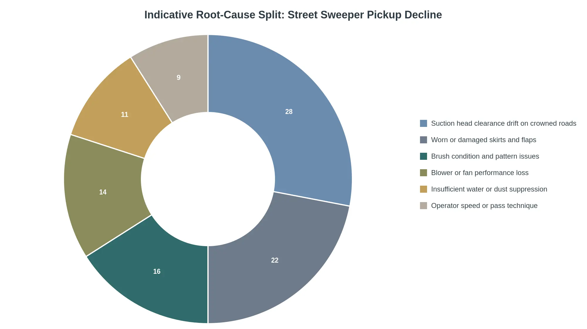
Root-Cause Split: Where Sweeper Pickup Actually Leaks Away
Before you reach for the wrench, it helps to know where the odds are stacked. The doughnut chart below distributes typical pickup-loss complaints across the six failure modes that dominate municipal shop work orders. It is a prioritization tool, not a diagnosis: use it to sequence inspections, then confirm each suspect with gauges, feeler shims and a test pass.
How to Read the Split
Suction head clearance drift on crowned roads (28%). The largest single slice, and the one crews usually check last. The head rides the high side and opens up on the low side, so the nozzle gap grows with no visible damage. A 6 mm drift on one edge is enough to trade vacuum for a curtain of dust and a trail of grit along the gutter line.
Worn or damaged skirts and flaps (22%). Rubber that has curled, torn or glazed stops sealing. Once the curtain leaks, the fan pulls atmospheric air instead of debris, and operators compensate by slowing down, which hides the real problem for weeks.
Brush condition and pattern issues (16%). Splayed bristles, excessive down-pressure, or a pattern that throws material past the pick-up zone all show up as “the sweeper isn’t picking up” even when the vacuum side is healthy.
Blower or fan performance loss (14%). Rarely a sudden failure. More often it is impeller erosion, a stretched or slipping drive belt, a partly collapsed flexible duct, or a clogged screen quietly stealing airflow.
Insufficient water or dust suppression (11%). Low spray volume does not reduce pickup directly, but it lets fines ball up and cling to the head, and it makes every miss visible as a dust plume. Nozzle blockage and tired pumps live here.
Operator speed or pass technique (9%). The smallest slice and the fastest to rule in or out: a five-minute ride-along with a stopwatch will tell you whether the machine or the driving is at fault.
An Important Caveat on the Numbers
Those percentages are an indicative planning estimate drawn from common fleet workshop patterns. They are meant to help supervisors order inspections and allocate shop hours. They are not a measured survey result and not a substitute for your own pickup-loss log. A fleet working mostly flat, well-drained arterials will see a smaller clearance slice; a fleet on narrow, heavily crowned residential streets under mature tree canopy may see a much larger one.
Turning the Chart into an Inspection Order
| Priority | Check | Typical Tool | Time on Bay |
|---|---|---|---|
| 1 | Nozzle gap, four corners, on the crown | Feeler gauge / shims | 15 min |
| 2 | Skirt and flap seal, all four sides | Hand check, straight edge | 10 min |
| 3 | Brush pattern and down-pressure | Chalk test, pressure gauge | 20 min |
| 4 | Fan drive, duct, screen | Tachometer, visual | 30 min |
| 5 | Spray nozzles and pump output | Flow test | 15 min |
| 6 | Operator pass technique | Ride-along observation | 20 min |
All six checks together fit inside a single shift, which is why the first move after a pickup complaint should be a measurement pass rather than a parts order. If the chassis itself is nearing replacement, it also pays to weigh rebuild costs against the alternatives in our guide to revitalizing aging street sweepers before committing to a major head and fan overhaul.
The Takeaway for Supervisors
Clearance drift and worn skirts account for half of the typical split, and both are cheap to inspect, cheap to correct and invisible from the cab. That is good news for maintenance planning. The other half sits in brush, blower and water work, where the money hides and where a ten-minute measurement pass saves the most diagnostic time. Log the gap you find, log the gap after adjustment, and the chart above stops being a planning guess and becomes your own fleet’s baseline.
Integrating Crown-Aware Clearance Checks into PM Intervals and Schedules
Most shops measure suction head clearance only after pickup quality has dropped. That is a repair response, not a maintenance program. The fix is procedural and cheap: make clearance a scheduled measurement, then let route geometry decide how often it repeats. For supervisors, that means writing crown awareness into the PM card itself rather than relying on operator complaints. If the fleet is mid-cycle on older units, plan a broader refresh alongside routine street sweeper maintenance so measurement, wear parts and adjustments land in the same shop window.
Step 1: Classify Routes by Crown Severity
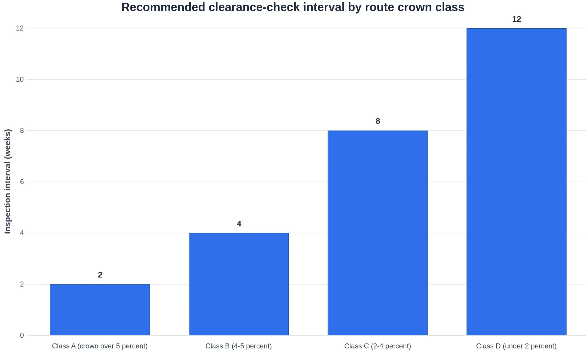
Crown is the variable that quietly sets wear rate. A head tuned on a flat pad opens up further as the crown steepens; past about 5 percent the downhill skirt stops sealing and the head loses airflow it cannot recover. Grade every route once, then attach an inspection interval to the class.
| Route class | Crown severity | Target clearance band | Check interval | Notes |
|---|---|---|---|---|
| A | Over 5 percent | 8-10 mm at the crown side | Every 2 weeks | Highest skirt and flap wear; measure inner and outer edges |
| B | 4-5 percent | 8-10 mm at the crown side | Every 4 weeks | Common on older residential grids |
| C | 2-4 percent | 10-15 mm | Every 8 weeks | Standard municipal profile |
| D | Under 2 percent | 10-15 mm | Every 12 weeks | Flat arterials, parking lots, industrial aprons |
Step 2: Bundle the Measurement with Work You Already Do
Never book a separate appointment for clearance alone. Pair it with skirt inspection and brush pattern checks, which already pull the machine into the bay.
- Measure the skirt-to-ground gap at four corners of the head.
- Judge the brush pattern on a chalked pad before the head is adjusted, not after.
- Verify readings on an actual crowned stretch, because a flat-bay setting reads differently in service.
One bay visit therefore confirms three failure modes: worn skirts, wrong brush contact and lost clearance. That keeps a municipal street sweeper working instead of parked twice for the same job.
Step 3: Adjust for Seasonal Reality
Wear is not linear across the year. Two seasonal shifts matter most.
Abrasive material load. Winter grit, sand, de-icing residue and spring construction silt all cut skirt life faster. Expect clearance to move quicker in the six weeks after the last salt run.
Surface condition transitions. Fresh chip seal, milled patches and frost heave change the effective crown. A route graded Class C in July can behave like Class B in March, so re-grade routes after any resurfacing or freeze-thaw cycle.
Step 4: Staffing, Tooling, and Traffic Control
Assign one technician plus a spotter, or a driver-technician pair, so measurement happens with the machine locked out and the head lowered. Tooling is modest: gooseneck or feeler gauges, a steel tape, a laser distance meter, chalk, a torque wrench and the OEM clearance specification sheet.
On an active carriageway, treat the check as a work zone. Arrow board or beacon on, cone taper behind the unit, high-visibility clothing, radio contact, and no work under a raised hopper. Where traffic cannot be managed safely, move to a low-volume window or a designated off-street pad and log the substitution.
Step 5: Record Fields That Enable Trend Analysis
Free-text notes will not support decisions. Standardize the card with: date, unit number, hour meter and odometer, route class and route ID, crown reading at the site, left/center/right clearance in millimeters, gauge type, skirt condition, brush remaining percentage, ambient and surface conditions, technician initials and corrective action taken. Six months of those fields will show a wear rate per 1,000 kilometers, the number that justifies either adjustment intervals or replacement.
Out-of-Cycle Triggers: When to Check Immediately
Run an unplanned clearance check when any of the following occurs:
- Visible drop in pickup, with a fine dust trail or a wet stripe behind the head.
- Operator reports the head skipping, chattering or riding high on one side.
- Skirt or flap replacement, or any head component change.
- Brush replacement, core swap, or a change in brush down-pressure settings.
- Hydraulic or vacuum loss that has been repaired on the suction side.
- Resurfacing, chip seal, milling or patching on a classified route.
- First snowfall response and the first full week after the de-icing season ends.
- Two consecutive PM cycles showing a downward clearance trend of 1 mm or more.
Escalating Repeat Findings into Capital Planning
Track repeat findings as a signal, not a nuisance. Escalate when the same unit needs re-shimming twice in one quarter, when wear exceeds roughly 1 mm per 1,000 kilometers, when two consecutive readings fall below the minimum band, or when the head plate shows cracking or distortion that no adjustment corrects.
At that point the conversation moves from a shop ticket to a budget line: head replacement, weld repair, or rotation to flatter routes. Bring the trend data, not an opinion, into the capital review cycle, and stage replacement ahead of the season when downtime hurts most.
Specification and Procurement: Replacement Heads and New Sweeper Units
On a crowned network the suction head never sees a flat plane. It spends its working life on a slope that changes sign at the centerline, so every millimeter of clearance is a compromise between picking up at the gutter and dragging the skirt over the crown. Clearance belongs in the specification, not in the maintenance afterthought column. Buyers who write clearance, articulation and wear-part support into the purchase documents get units that hold their set height for years. Buyers who don’t spend the next decade with crews chasing pickup quality, as outlined in this guide to revitalizing city street sweepers.
Questions to Put to Suppliers Before Award
Ask these in writing and require written answers as part of the bid. Verbal assurances about “self-adjusting” heads rarely survive the first winter of grit.
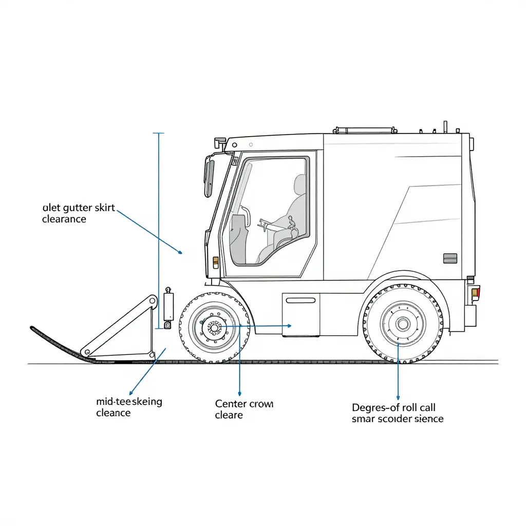
Clearance adjustment range. Ask for total vertical travel in millimeters, the mechanism (shim stack, threaded link, slotted bracket or hydraulic actuator), and whether each side adjusts independently. Confirm the achievable band from fully raised to fully lowered, with and without the blower running, and whether adjustment is possible with the head in place. A head with only 10 mm of usable adjustment is effectively pre-set at the factory.
Head articulation and crown compensation. Ask how many pivot axes the head has, the roll range in degrees relative to the sub-frame, and whether the head self-levels on casters or is rigidly hung. On a crown of 2 to 3 percent, a head that cannot roll will unload the gutter skirt while burying the crown-side skirt, the classic pattern of uneven wear.
Skirt material and replacement economics. Request compound (natural rubber, EPDM, urethane or nitrile), thickness, Shore A hardness, segment count and cost per segment. Ask for expected service life in curb-miles rather than months, and whether segments are sold individually or only as full kits.
Frame construction and repairability. Ask for material grade, wall thickness, welded versus bolted construction, and whether pivot points use replaceable bushings. Confirm which frame members come as individual parts and whether a bent head frame can be straightened to tolerance or must be replaced outright. For comparable body build standards, see this overview of choosing municipal truck bodies.
Wear parts availability. Request part numbers for every consumable, current lead time, minimum order quantity, and a written commitment on how long those parts stay in production after delivery. A sweeper body typically serves 10 to 12 years, and a skirt compound quietly superseded in year four creates clearance drift nobody can diagnose.
| Specification item | Ask the supplier for | Record kept in file |
|---|---|---|
| Clearance range | Total travel in mm; per-side adjustment; mechanism type | Signed technical data sheet |
| Articulation | Pivot axes; roll range in degrees; caster loading | Drawing with dimensions |
| Skirts | Compound, thickness, Shore A, segment count, unit price | Price schedule + sample |
| Frame | Grade, wall thickness, bushed pivots, part-level availability | Bill of materials by line item |
| Wear parts | Part numbers, lead time, production-support term | Parts appendix to the contract |
Requiring Measured Clearance Verification at Handover
Do not accept a handover based on a visual check. Specify the verification procedure and make delivery acceptance conditional on the documentation:
- Defined condition. Measurements taken with the water tank full, tires at specified pressure, blower at operating speed and the unit on a level pad of known crown profile.
- Defined points. At least five readings per head: left gutter, left mid-slope, centerline, right mid-slope and right gutter, each recorded to the nearest millimeter.
- Defined tools and datum. Gauge blocks or a calibrated depth gauge, with the measuring datum stated on the sheet so future readings compare.
- Signed record sheet. Buyer and supplier representative both sign the clearance chart at delivery, with a re-check scheduled at the first 50-hour service and the results attached to the unit file.
- Tolerance statement. Out-of-tolerance readings trigger adjustment before acceptance, not a note in the remarks column.
That signed chart becomes the baseline for every future wear inspection. Without it a crew has no reference point, and the problem usually surfaces only when pickup quality drops.
Why Factory-Direct Build and Stable Parts Support Reduce Clearance Drift
Clearance drift is rarely a single failure. It accumulates: a frame that flexes at the pivot, a skirt compound reformulated without notice, an adjustment linkage that goes obsolete, a crew compensating with shims instead of a documented setting. Buying through a dealer with factory-direct build options and multiple Chinese manufacturing partners keeps those variables under control. Build sheets can specify skirt geometry matched to the local crown profile and road mix, frames can be ordered in the wall thickness the duty cycle actually needs, and the parts list issued at delivery stays traceable to the same production source. As a B2B civic truck supplier, the dealership’s job is to hold that configuration on file and support the unit through its service life, the same principle behind efficient custom municipal truck builds.
Procurement Takeaway
Write clearance range, articulation, skirt specification, frame repairability and parts-support terms into the bid documents. Require a signed, measured clearance chart at handover and again at the 50-hour re-check. Then keep the head on the documented baseline instead of adjusting by feel. On a crowned network that discipline is the difference between a sweeper that picks up for a decade and one that is back in the shop every season.
FAQ: Suction Head Clearance on Crowned Roads
What clearance value should we use on crowned roads when the manufacturer specifies a single figure?
Use the single figure as the setpoint at the low side of the head, which on crowned roads is the curb-side edge, and let the street-side edge sit higher by the measured crown drop across the head width. Never set the average of the four corner readings equal to the spec: that buries the curb-side skirt and wear shoe in the pavement while the street-side edge leaks air. Cap the offset at the manufacturer’s stated tolerance, typically plus or minus 3 mm (1/8 in). If the crown drop across the head is larger than twice that tolerance, the problem is head mounting geometry, not the number on the decal, and the pivot, lift linkage and wear shoes need inspection before suction head clearance gets touched again.
How often should suction head clearance be re-measured?
Measure at 50 hours after any head, wear shoe or skirt replacement, then at 250-hour intervals on routes with pronounced crown or heavy grit load, and weekly on high-hour units. Add an immediate four-point check after any curb strike, hydraulic drift event, or complaint about street sweeper pickup performance. Always use the same four reference points, front and rear on both the curb side and street side, so the trend line stays comparable. Crews that only measure after pickup drops are reading a symptom, not a measurement. Guidance on scheduling sweeper upkeep alongside other seasonal fleet work is in this look at how to revitalize your city street sweepers.
Is shimming one side of the head an acceptable permanent fix?
No. Shimming is a legitimate diagnostic that confirms head tilt is causing uneven wear, and a documented temporary shim is fine while parts are on order. As a permanent repair it preloads the pivot, misaligns the blower-to-head seal plane and shifts load onto the frame, which later shows up as cracked brackets and uneven skirt wear. Fix the root cause instead: worn pivot bushings, bent lift arms, sagging springs, mismatched wear shoe thickness. Record every shim you install so the next technician knows the geometry was already compromised.
How do we distinguish clearance loss from blower or skirt degradation?
Work in sequence: gauge suction head clearance at all four points first, then run a chalk or strip test for skirt sealing, then check duct joints and the head-to-blower seal for leaks, and only then evaluate blower output with a vacuum gauge and fan drive amperage. If the numbers are in spec and the machine still leaves a trail, the fault is airflow or sealing, not clearance. Skirt degradation looks like hardened rubber, curled edges or gaps at the corners; blower degradation looks like a vacuum drop at normal clearances, often with impeller tip wear or a slipping drive.
Does crowned-road wear justify a different skirt material or a heavier specification?
Crowned roads concentrate abrasion on the curb-side skirt and outer wear insert, so that is where a material upgrade pays off, not as a blanket heavier spec. Choose reinforced two-ply rubber with a fabric insert, or a urethane insert, for the curb-side section only, and keep flexible rubber where the skirt must conform to crown curvature. Overspecifying durometer across the whole head reduces conformity, lifts the head and increases drag and fuel burn. Segment or sectional skirts with replaceable curb-side wear strips give the abrasion resistance without sacrificing the seal.
What records should be kept to support replacement requests?
Keep a per-unit clearance file with date, hour meter, route and crown classification, all four measurement values, gauge ID and calibration date, ambient temperature, parts installed and technician initials. Attach photographs of the wear pattern and skirt condition, plus shim history and follow-up measurements after repairs. Retain the file for at least 24 months or two full skirt replacement cycles, whichever is longer. A trend line showing how fast street sweeper suction head clearance drifts on crowned sections is what turns a replacement request from an opinion into a defensible capital justification.
Closing Takeaways: Engineering the Suction Head Around the Crown
Crown geometry is a design condition, not a defect to tune out. The pavement rises toward the centerline and falls into the gutters, so the gap between head and road cannot be constant across the sweep width. A setting correct at the curb line sits too high over the crown; a setting that hugs the crown drags the gutter. A single head-height number on a spec sheet is therefore incomplete, and an adjustment routine that ignores cross slope produces a machine that cleans one side of the lane and smears the other.
Declining pickup is the event that should open the work order. Crews notice lost vacuum performance long before anyone measures clearance, and that observation is a legitimate, repeatable trigger for a scheduled inspection rather than a reactive repair. Departments that build the trigger into their street sweeper maintenance programs get ahead of the wear curve instead of chasing it.
The wear pattern records where contact happens. Reading wear strips, side skirts and frame pivots left against right separates crown-side scuffing from curb-side dragging, and a geometry problem from a damaged or misaligned component. That distinction keeps parts spending in check: replacing a wear strip without identifying which side and which component caused the contact just restarts the cycle.
The correction sequence matters as much as the measurements. Vehicle ride height first, because tire pressure, suspension condition and load distribution set the reference plane everything else is measured from. Then the head frame, because bent structure, worn pivots and loose mounting points shift the head’s attitude independently of the hydraulic setting. Clearance last. Any other order encodes an unresolved upstream fault into the final adjustment and guarantees a repeat visit.
Key Takeaways for the Maintenance Policy Note
- Verify ride height, tire pressure and suspension condition before touching any head adjustment, and record both values on the inspection sheet.
- Schedule the clearance check on the first measurable drop in pickup performance, not at the next fixed service interval.
- Compare wear strips and skirts left against right to identify crown-side versus curb-side contact before ordering parts.
- Repair frame damage, worn pivots and suspension faults first; set head clearance only against a known-good reference plane.
- Document clearance at both the curb line and the crown after every adjustment, and compare both readings at the next inspection.